Fruit Machine - PS8 Steam
PS8 Steam
Title
Projects
Fruit Machine Mechanism
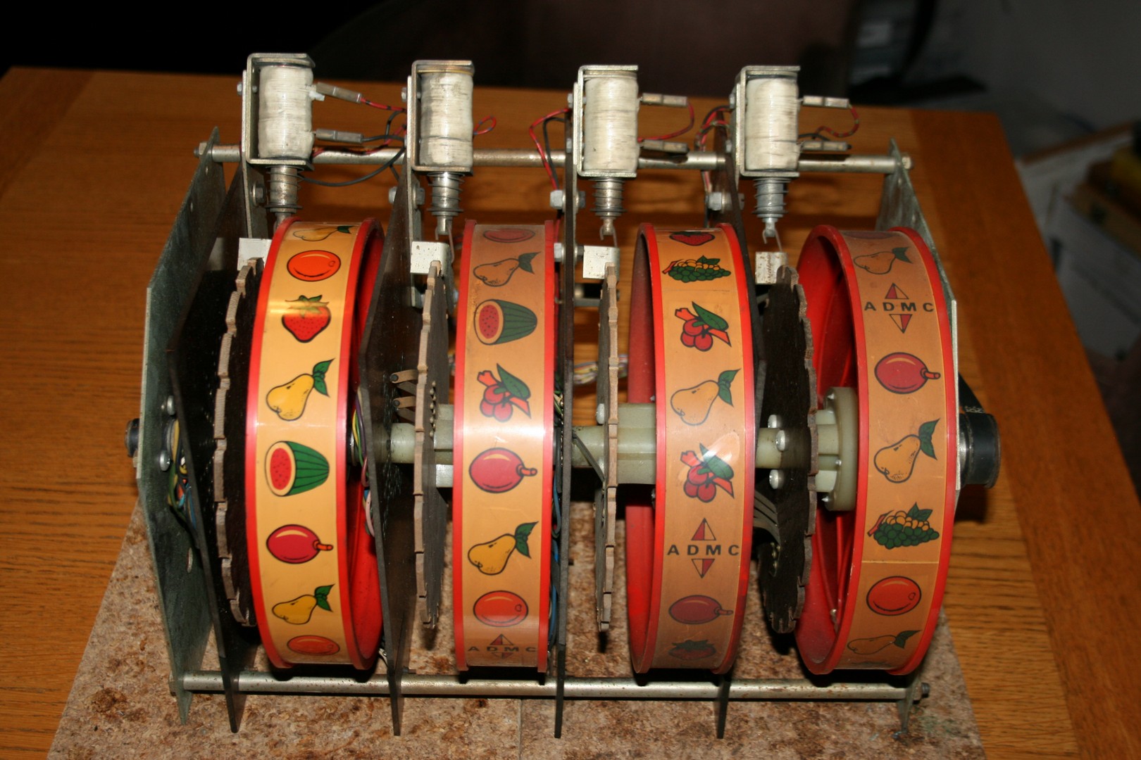
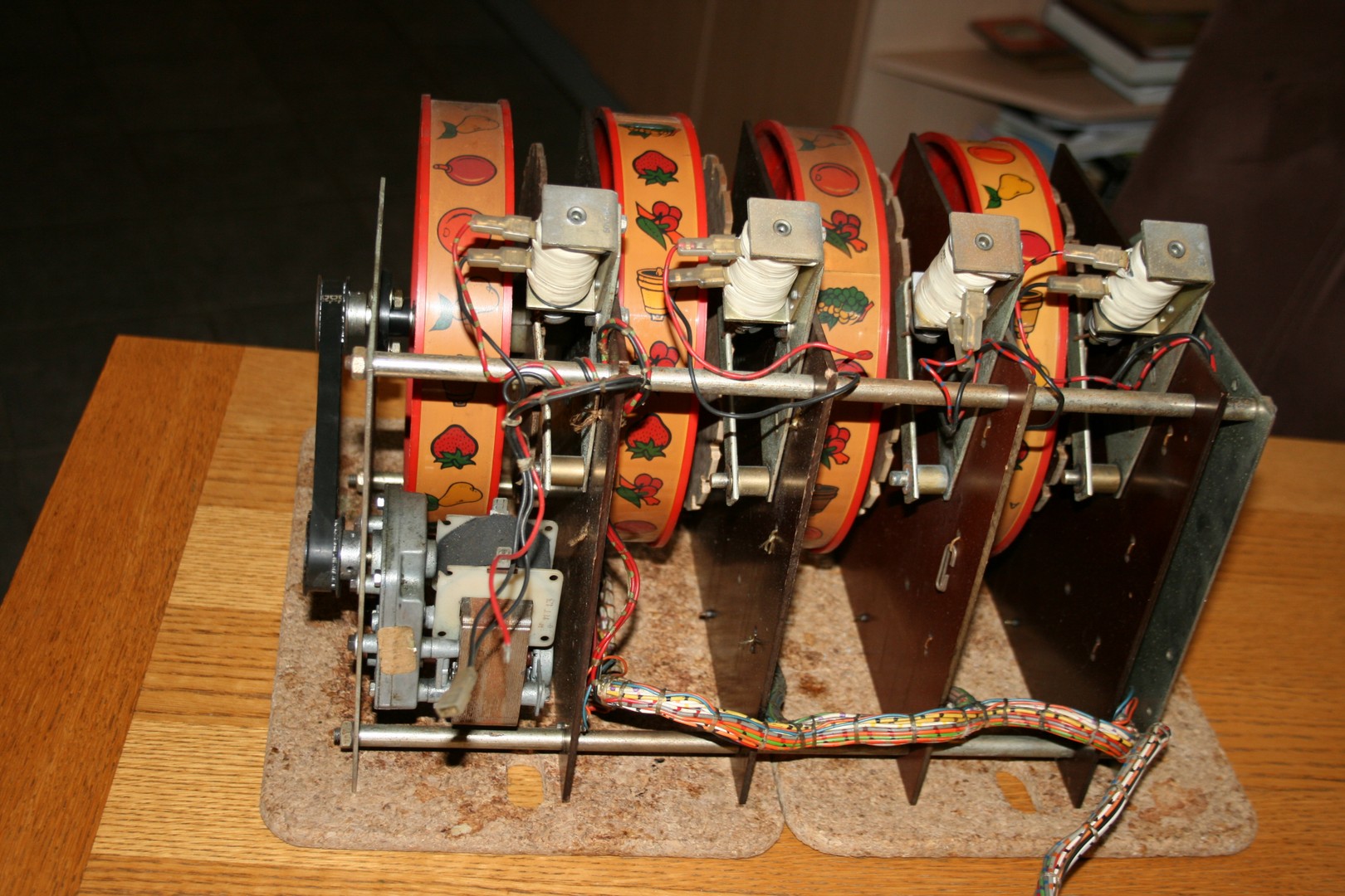
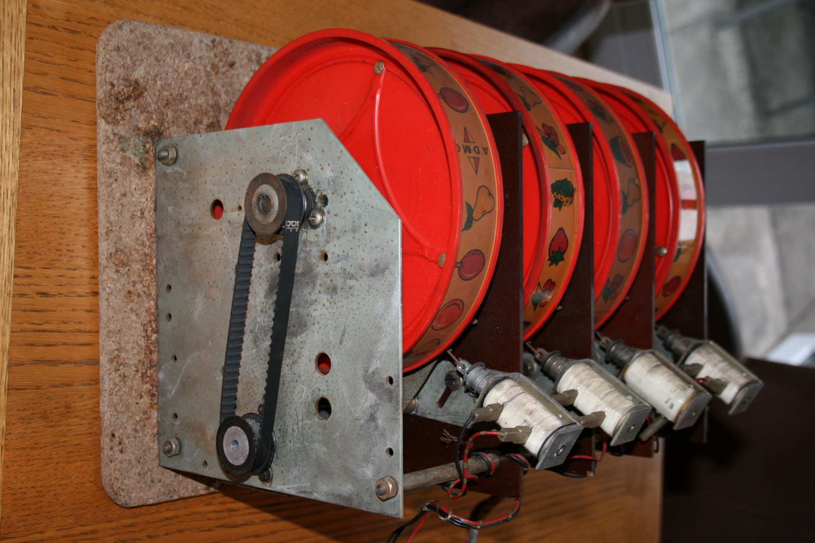
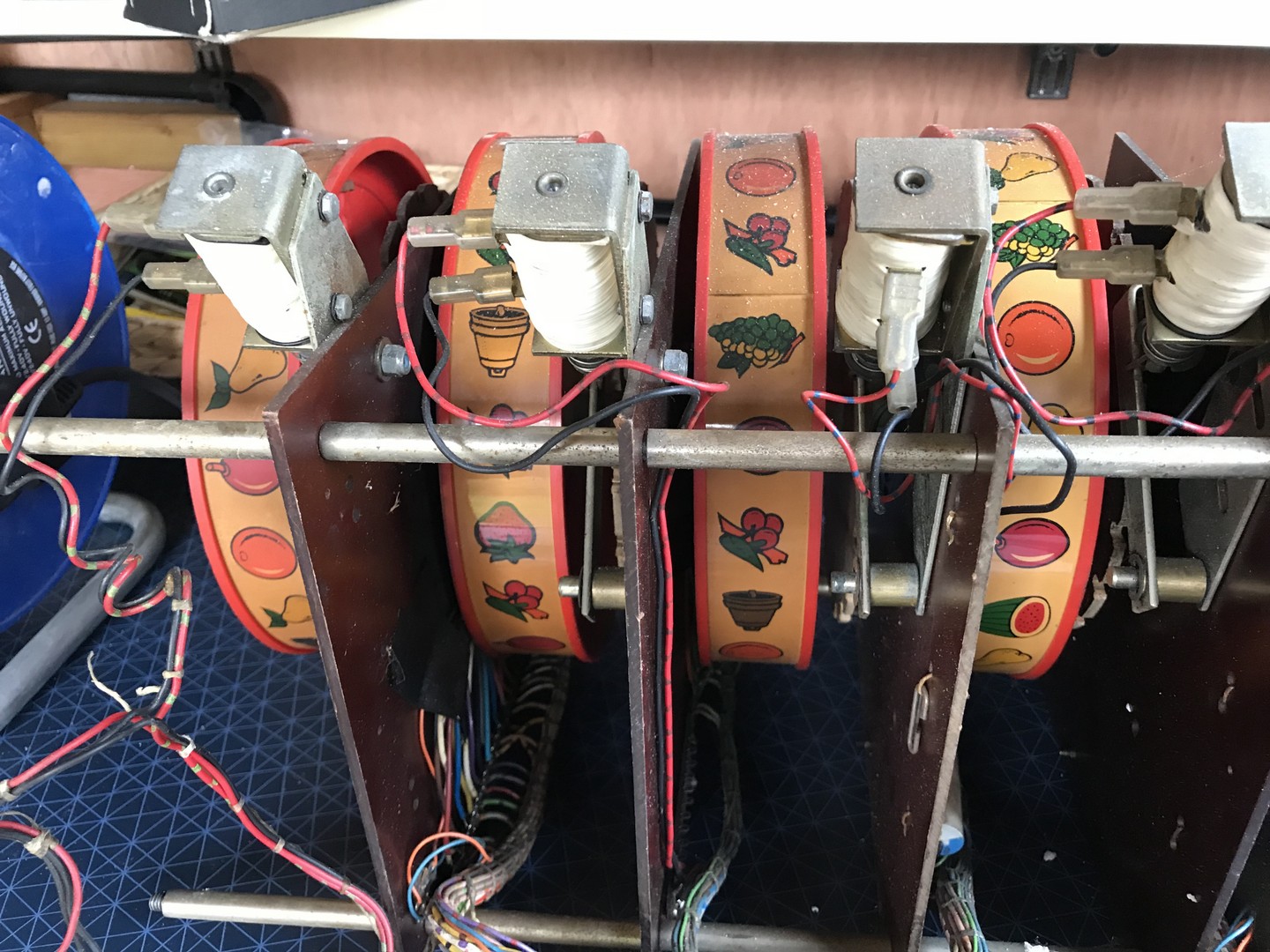
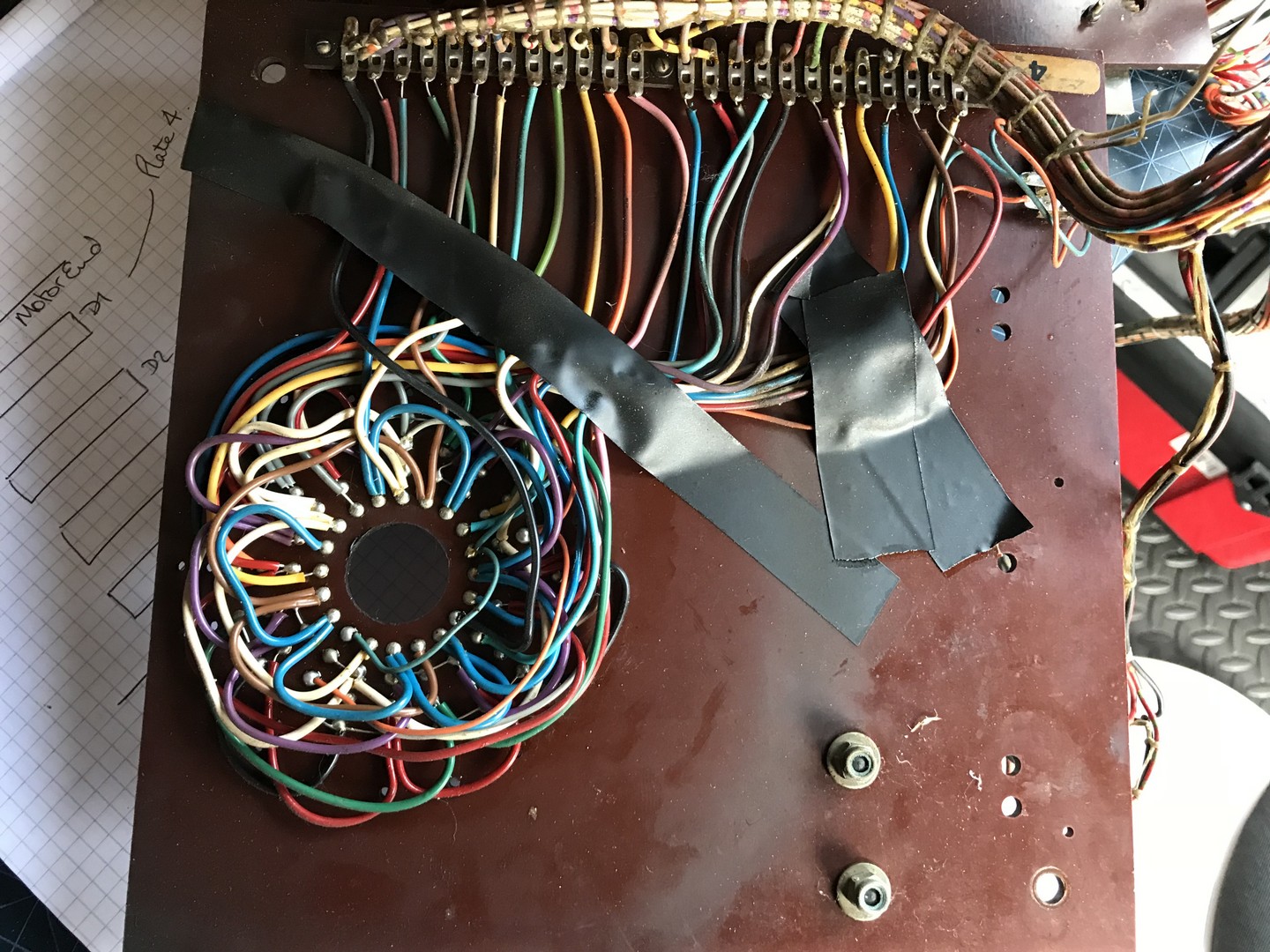
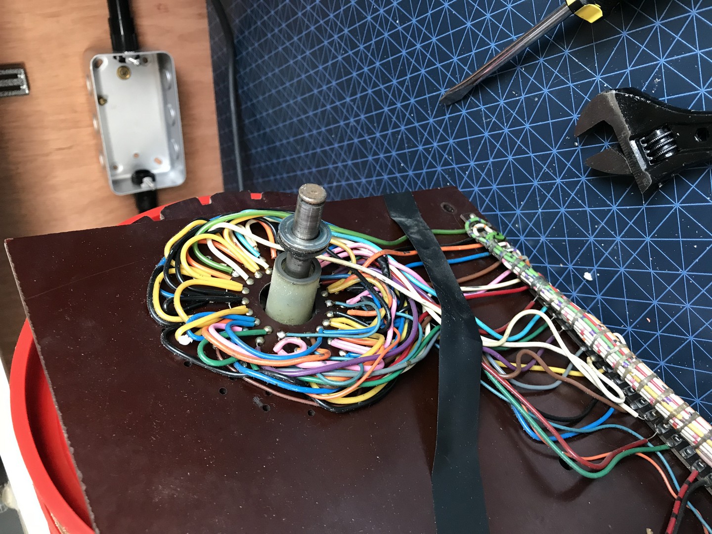
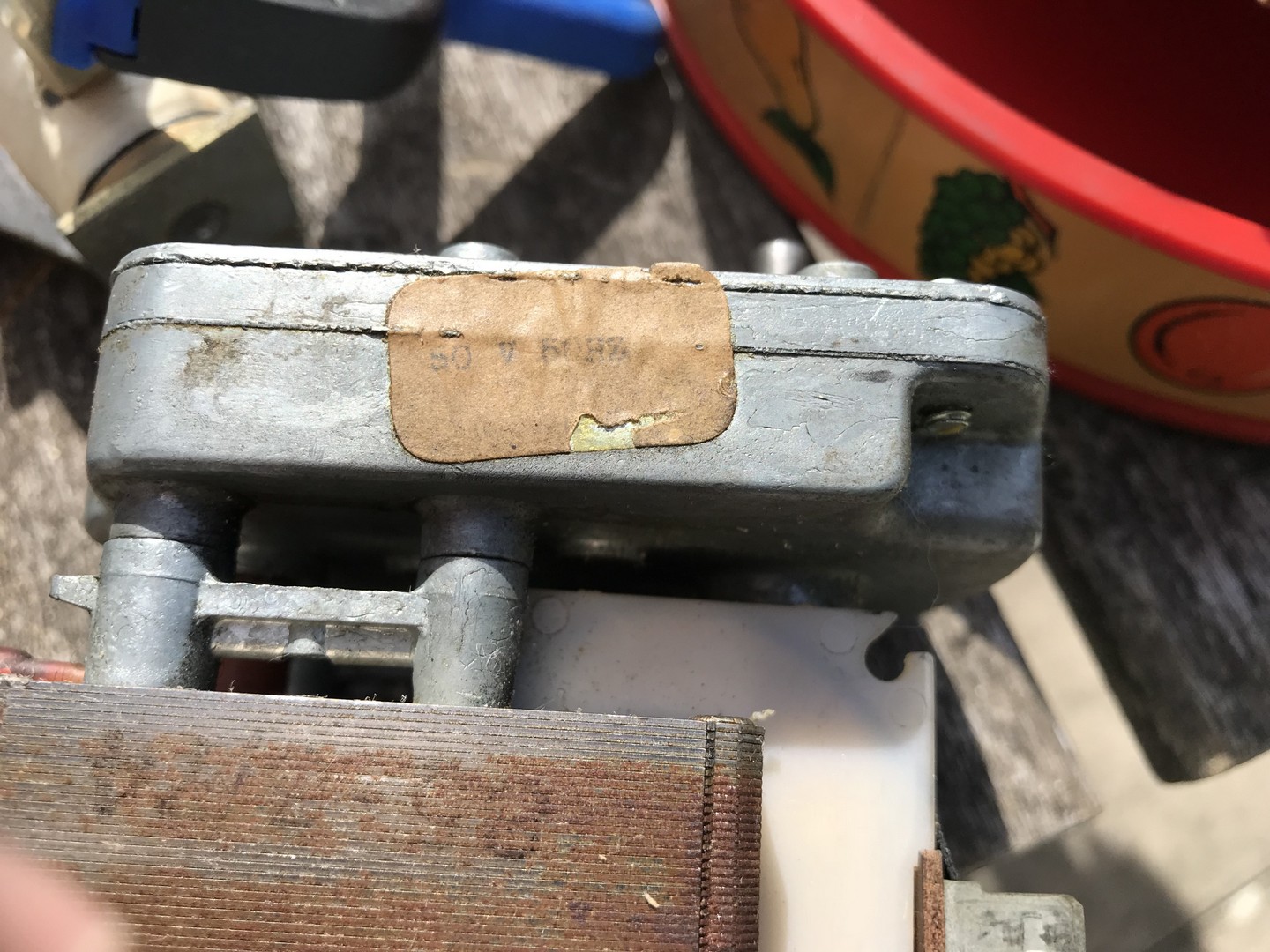
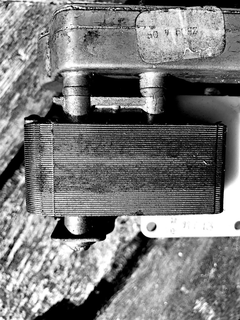
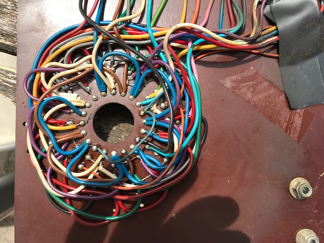
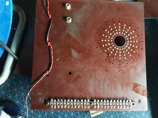
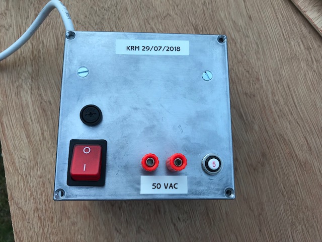
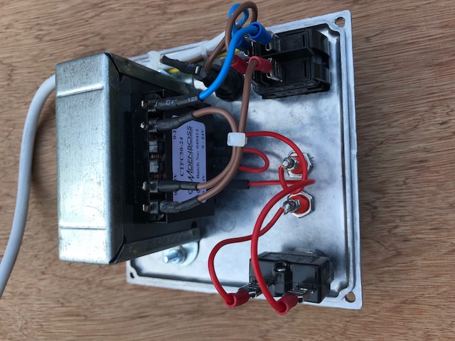
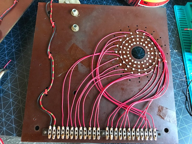
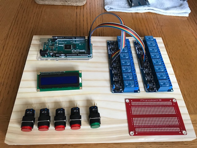
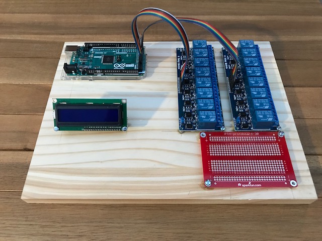
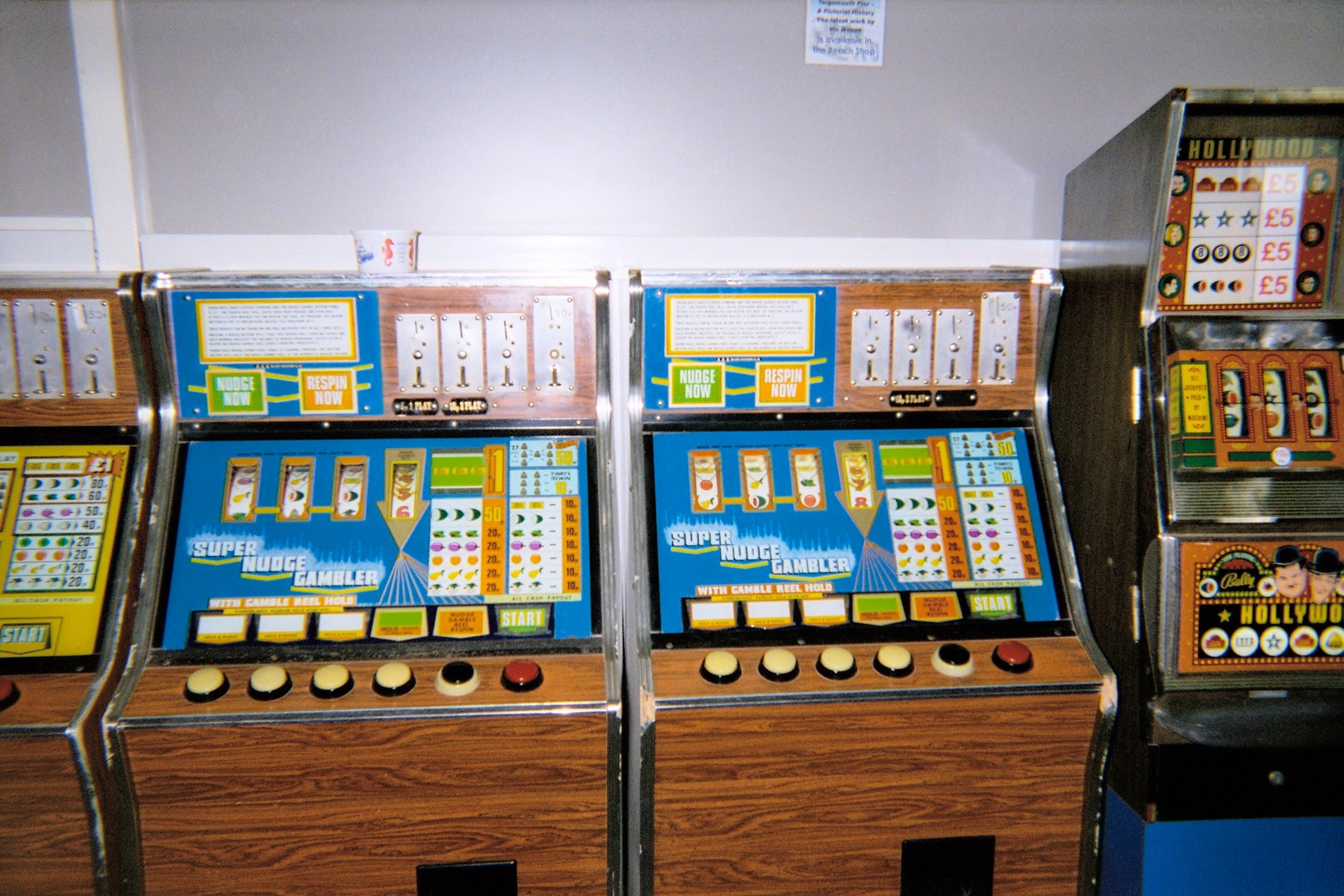
3rd June 2018I came across this fruit machine mechanism at a car-boot type market at a vintage car and bike show, and for £20 I couldn't resist it. No idea what I am going to do with it however. All four drums are on a single shaft and each has a solenoid which either lets it rotate or stops the drum. The drums being a friction fit on the shaft. One each drum there are four phosphor bronze strips which make contact with a fixed disk. Each of the contacts is brought out to a multi-way plug. Single shaded pole motor drives the shaft. So, all I can tell at the moment is I can let drums rotate or not, and I can detect the position of the drums. Not sure to what degree I can read the drum positions yet. Motor seems to be stuck solid for now.4th June 2018The only brand name (if it is a brand) is ADMC on the drums. Possibly a 'Whoopsie Gambler' or a 'Whoopsie Nudger'. The nudge button moved the drums in the backwards direction and against the natural direction of the phosphor bronze strips - which apparently was a big cause of failure. Not sure about this, my mechanism can only rotate in one direction!12th June 2018Bought the components for the power supply.24th June 2018Dismantled the fruit machine mechanism! The motor isn't stuck, but has a gear box added with a big reduction, and I was trying to turn the output shaft! Bit of web searching and very carefully reading the very faded labels on the motor identifies it as a 50V motor. It's a shaded pole motor, so AC of course.With the motor on the bench, and 50VAC applied, it turns perfectly. The torque on the output shaft is huge!The solenoids also work perfectly fine with 50VAC. I assume there was a beefy 50V transformer in the machine somewhere.The cellulose labels strips were filthy and somewhat faded. They look better now they are cleaned up.The wiring on the back of each of the drum boards looks a nightmare, and I am considering what to use to document this and perhaps produce a circuit diagram. Each board is differently wired.Three of the drums each has two phosphor bronze contacts which short out pins on the fixed board. One pair shorts the inner two rows of pins, and the other the outer two rows. One drum only has a single shorting strip and just two rows of pins.27th June 2018Written the code for the micro-controller! Arduino 2650 - because of the large number of i/o pins. In addition to the Arduino, Ihave two 8-way relay boards and an LCD display. The 16 relays connect one-to-one with pins on the Arduino. The relays are used to switch current to the motor, the four drum solenoids, and the lights in the start button and four nudge buttons. V1.2 (not finished) is hereThe LCD display included a I2C controller, which means it needs just two pins to talk to it. I will put up the circuit diagrams and the code shortly. In fact, I will put up the code for V1.2 now. I need 20 digital inputs from the drum sensors and using 20 pins for this seems wasteful, so I am using three 4021 shift registers. This means I can read 24 inputs with just three wires from the Arduino. With appropriate jiggling of the latch and clock I can read in all inputs into three bytes. All 20 pins are wired in parallel across the four drums, but I can select which drum I wish to read. The four nudge button are wired one-to-one with Arduino pins. I need to think what to do when someone wins - a proper old-school bell perhaps?30th June 2018Built a new 50VAC power supply in a small diecast box. 50VA transformer, 5A thermal cutout on the secondary, lluminated mains switch and 20mm fuse. Diecast boxes are easy to drill and very easy to file away, so creating a square hole for the mains switch was remarkably quick. I thought I had ordered a cable gland for the mains lead, but apparently not - something for next weekend. Pictures alongside.So, I stripped off all the old wiring from the drum sensor boards. Pictures before and after alongside. This seems terrible I know and if it were a museum piece this would be a sacrilege, but this is a home project and I haven't the time to work out what is going on with all of the original wiring. Each panel was wired differently I should add. Much of the original logic was effectively coded in this wiring. I promise that if I buy a compete machine of a similar vintage I wont do this again.1st July 2018Mounted all the controller components on a (fairly chunky) piece of pine. The physical layouts and the ribbon cables dictate which pins are used, so the s/w will need to be updated to map them all correctly.Completed the re-wiring of the drum position contact boards. Started the re-assembly of the whole mechanism - this is hard work despite taking lots of pictures when I dismanteled it all. Actually very few parts left over, but sadly included a small brass bush from one of the drums, so it will need to come apart to refit that. I also straightened the phosphor-bronze contacts that had suffered over the years, but seem to have forgotten one of them. The belt has also stretched, and although the motor can be moved to re-tension the belt, it can't be moved that much. Generally belts like this are readily available, so I will need to buy a replacement.I have uploaded a short video below of the mechanism running albeit with a little manual help.6th July 2018Short video below of the second re-assembly of the fruit machine - and it all looks a lot happier! Belt seems to be OK.7th July 2018Attached the Arduino board to the relay boards to the fruit machine and ran it all. My code for the Arduino has a diagnostic mode that allows me to switch the motor on and off and individual solenoids, so I used that first to check all was OK. Passed those tests, so I switched it to game mode instead. I have uploaded a short video of the machine running. I really need to put the strips back on the drums as it will look so much better. Another quick video added with the strips back in place.8th July 2018Three 4021 chips for the shift register in place now. I can select each of the drums in turn, and the 20 wires from each in parallel connect to the the first 20 of the 24 (3 * 8) inputs to the shift registers. So now I can read the position of each of the drums when they come to a stop.Never having played fruit machines before, I still need to understand how the nudge and/or hold options were presented to the player. Needs a little more research.I believe the mechanism I have is from a Super Nudge Gambler - the pictures above include one of a pair of these machines that were once in an arcade in Teignmouth, UK. I have added a short video to the side showing the machine runnning when I presume it was being decommission from a customer.10th July 2018Just found four videos which I am sure feature my mechanism!https://www.youtube.com/watch?v=py-YLijLWHk, https://www.youtube.com/watch?v=24McqZBHQOY, https://www.youtube.com/watch?v=ZWzT8tVlnhk and https://www.youtube.com/watch?v=8xV4n6DdSRQ6th August 2018Useful info from the MPU Mecca Forum:
The reel mech was designed and built by Bell Fruit Manufacturing Nottingham in the 70s and originally used in mainly their electro mechanical club machines but some were found in AWP pub machines too.ADMC was a company that built conversions to fit mainly onto Bell Fruit machines with a glass and reel band change.7th October 2018Finally getting around to looking at the control for my fruit machine. V1 is working, and a short video is alongside.
Nice article about the company history: